ESP 8266 (NodeMCU) and TFT LCD ILI9341

I bought the Arduino and Esp8266 kit a long time ago but never really touched them till now. This is my first experiment that i wanted to craft a simple proof of concept (POC) in order to make things work. The purpose of this post is to show the matrix on the TFT 2.8 inches ILI9341 LCD screen.
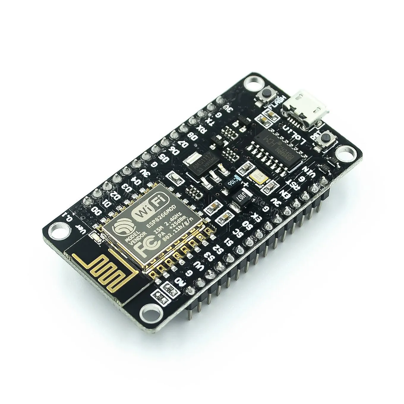
ESP8266 and NodeMCU Devboard
The ESP8266 is only a small module in which contains a processing chip, it supports Bluetooth and Wifi capability
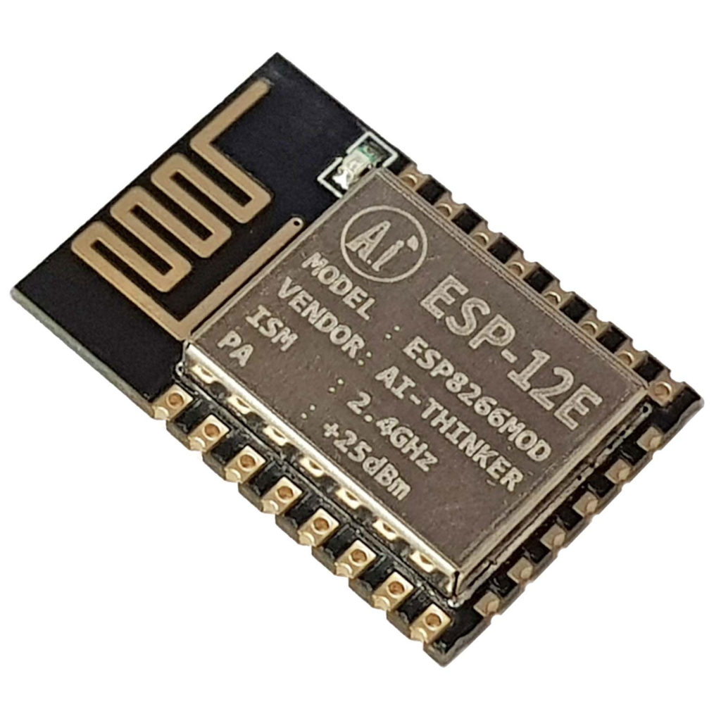
The NodeMCU in simple term is just a wrapper around the chip that indirectly connect to the ESP8266 PIN and expose them via pins on the board. We can see that the ESP8266 MOD is soldered directly on the board. The purpose of this approach is that it's easier to work with the module, we have something that's good enough to work with so we don't have to design and print the custom PCB board.
Even though the board has Wifi and Bluetooth capability, we won't tinker with these functionality in this post.
TFT 2.8 inches ILI 9341 screen
It's a screen module module that looks like this
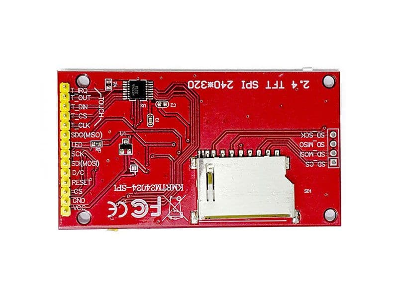
The screen support touch capability but we won't tinker with it in this post to keep things simple. One important things is that the screen works using the SPI protocol, so we will need some knowledge about the SPI protocol in order to wire the PIN between the board and the screen following the protocol.
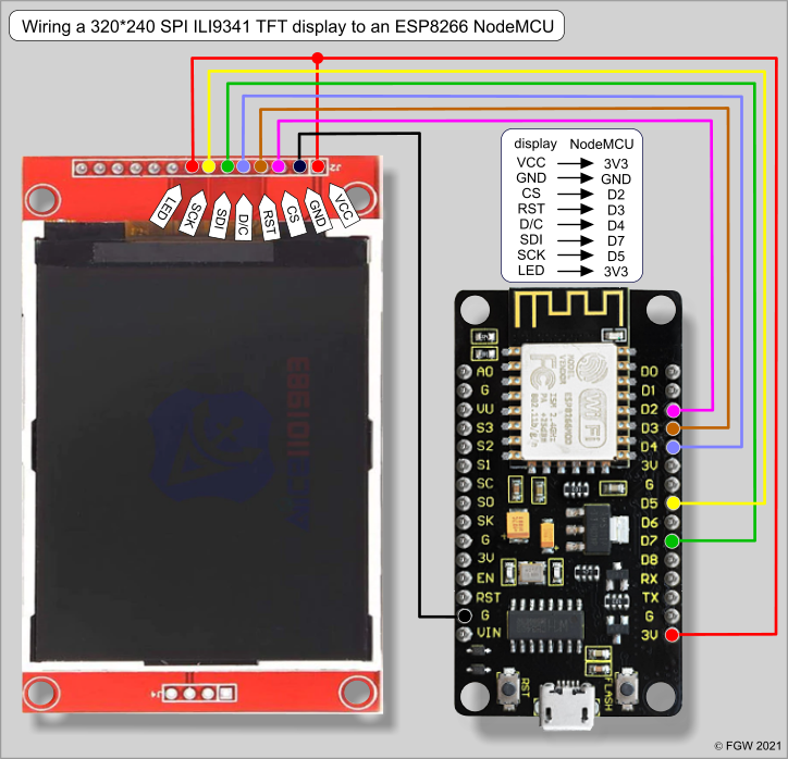
The SPI Protocol And Wiring
Not coming from the electricity world, i think the simplest way to explain it is like the following statements.
There are Pins on the screen, we will have to connect them to the board (by either using jumper wire or soldering them directly to the board). A couple of pins on the screen must be correctly in a certain way. Others are more flexible, there are more than 1 pin that they could be connected to, so connect to either one of them should work. Link: https://thesolaruniverse.wordpress.com/2021/05/02/wiring-an-ili9341-spi-tft-display-with-esp8266-based-microcontroller-boards-nodemcu-and-wemos-d1-mini/
Arduino IDE and code
I used Arduino IDE for the coding environment because i haven't got a lot of experience yet, i will find a way to use VSCode instead but Arduino IDE is good enough for now.
We will need to install the TFT_eSPI library in the IDE as follow
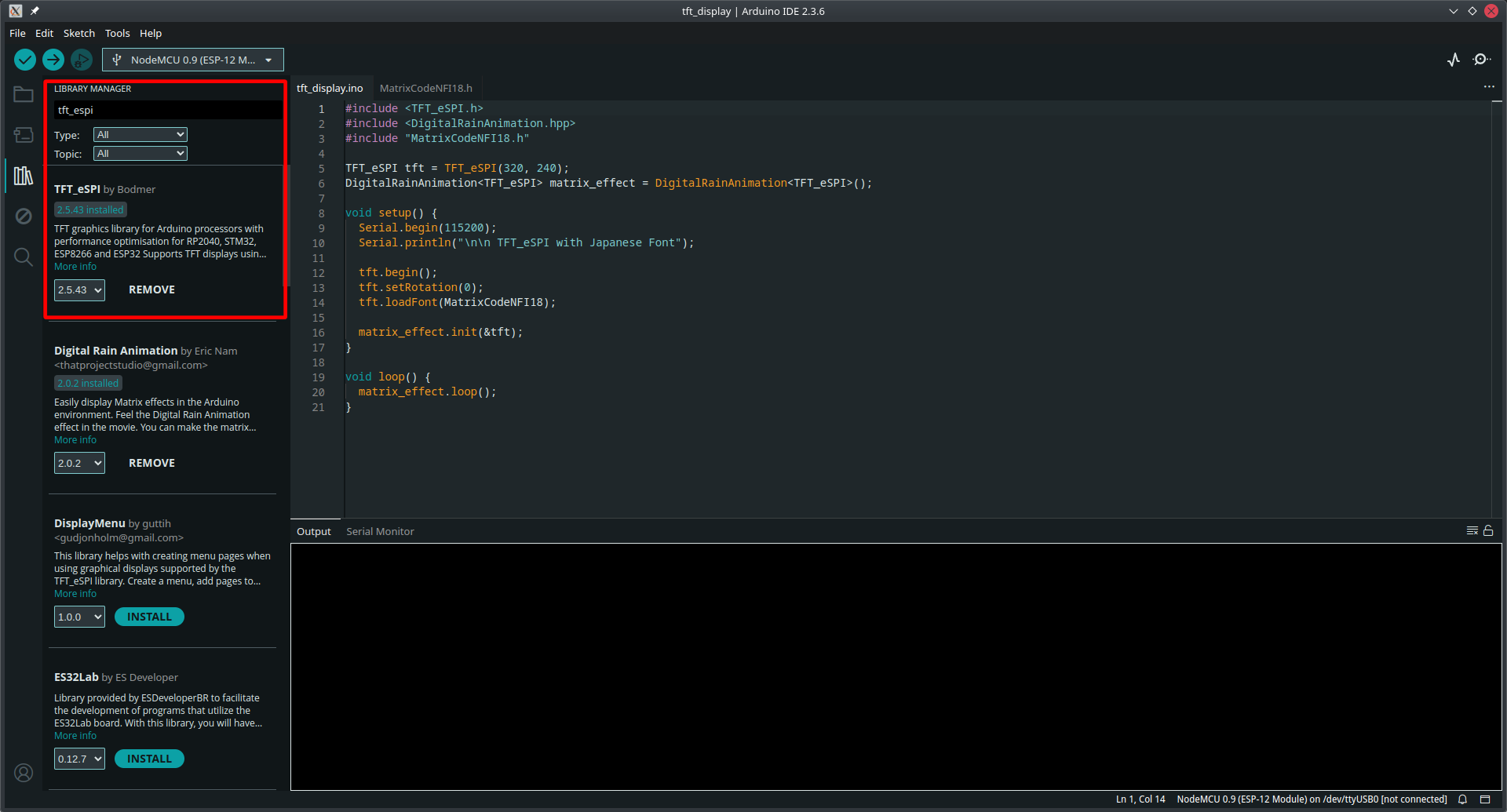
After installing the library, we will have to modify the code in the library, the library is installed to ~/Arduino/libraries/TFT_eSPI . We will have a look into the User_Setup.h
// For NodeMCU - use pin numbers in the form PIN_Dx where Dx is the NodeMCU pin designation
#define TFT_MISO  PIN_D6  // Automatically assigned with ESP8266 if not defined
#define TFT_MOSI  PIN_D7  // Automatically assigned with ESP8266 if not defined
#define TFT_SCLK  PIN_D5  // Automatically assigned with ESP8266 if not defined

#define TFT_CS    PIN_D8  // Chip select control pin D8
#define TFT_DC    PIN_D3  // Data Command control pin
#define TFT_RST   PIN_D4  // Reset pin (could connect to NodeMCU RST, see next line)
We will have to double check if the pin on the screen is wired correctly as defined in the code here. Otherwise, it won't work.
Additionally, we will need to install another library called DigitalRainAnimation.
The Code
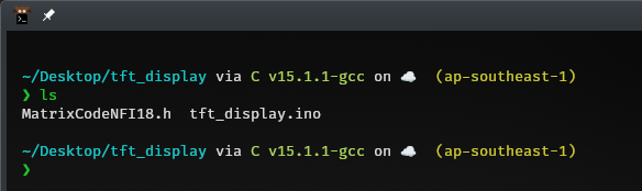
First, we will have to create a folder to save the sketch. Then we will create 2 files as following. The .ino file is the actual code that Arduino IDE will compile.
The other file is just additional data we will include in the .ino file
Here's the code
#include <TFT_eSPI.h>
#include <DigitalRainAnimation.hpp>
#include "MatrixCodeNFI18.h"

TFT_eSPI tft = TFT_eSPI(320, 240);
DigitalRainAnimation<TFT_eSPI> matrix_effect = DigitalRainAnimation<TFT_eSPI>();

void setup() {
  Serial.begin(115200);
  Serial.println("\n\n TFT_eSPI with Japanese Font");

  tft.begin();
  tft.setRotation(0);
  tft.loadFont(MatrixCodeNFI18);

  matrix_effect.init(&tft);
}

void loop() {
  matrix_effect.loop();
}
After that, we will connect the board to the USB port of the computer via a USB-A to USB cable. Then we select the drop down on the left, for BOARD we will select NodeMCU 1.0, PORTS we will select whatever available to us (there should be only 1 option available)
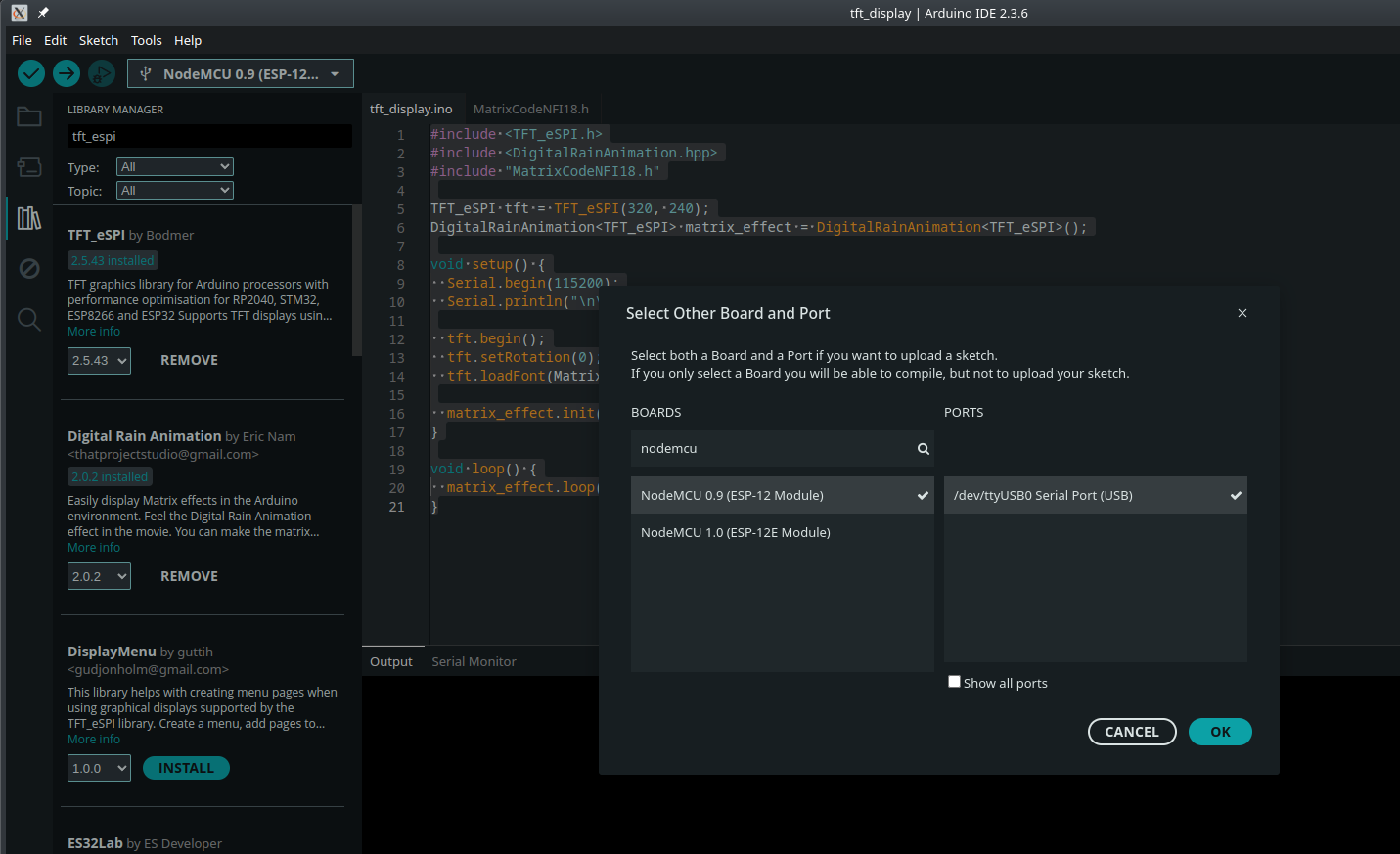
After everything is done, we will click the green with V icon so that the code could be compiled and transferred to the NodeMCU
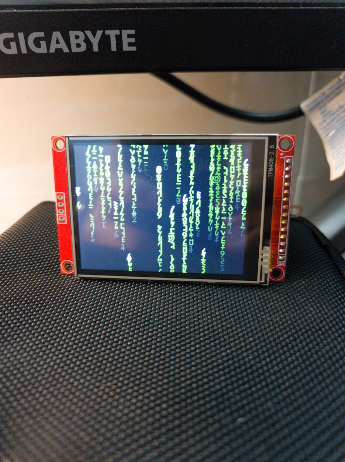
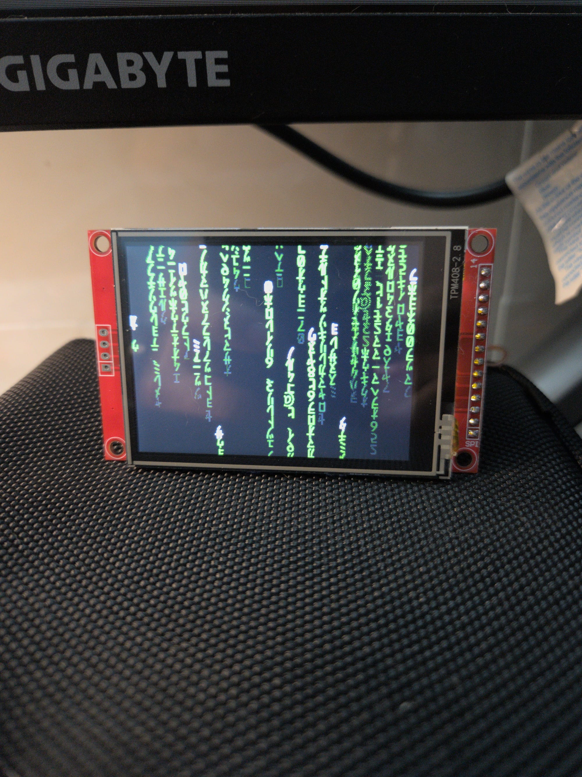
The Result